Solar Cart Documentation
This post is a work in progress!
The Cart
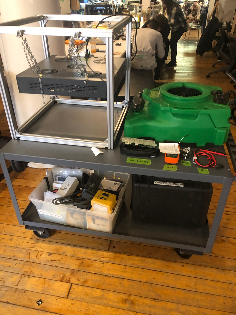
Meet the ITP Energy cart! This is your new best friend if you’re doing a solar-powered project, or any energy-related project at all. However, the cart must be understood and respected. This blog post is an introduction to the many things it has to offer.
What’s In The Cart?
THE PANEL
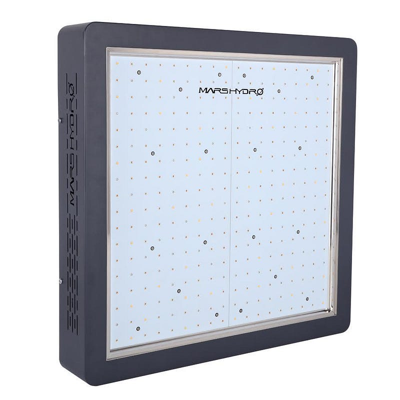
This is what we all came here to see. Designed as a grow lamp, presumably for indoor gardening enthusiasts, this lamp simulates the light of the sun, which makes it work great for solar projects!
How Powerful Is It?
Depends on the settings, and where you put your project! The lamp has two switches: “Growth” and “Bloom”, which offer different red/blue balances for different stages of plant growth. Since we’re not growing plants, however, we’re mostly concerned with how much power these different settings offer. Let’s break out the handy AMPROBE Solar meter, located right next to the panel on the cart!
This device can measure both Watts per meter squared and BTUs (if you need that for some strange reason). If you’re using the AMPROBE to test solar power, make sure it’s set to W/m2 and you’ve hit the “R” button to reset the range to measure ranges above 200 w/m2. If you see a decimal point between the numbers, you’re in the wrong range.
Some Context
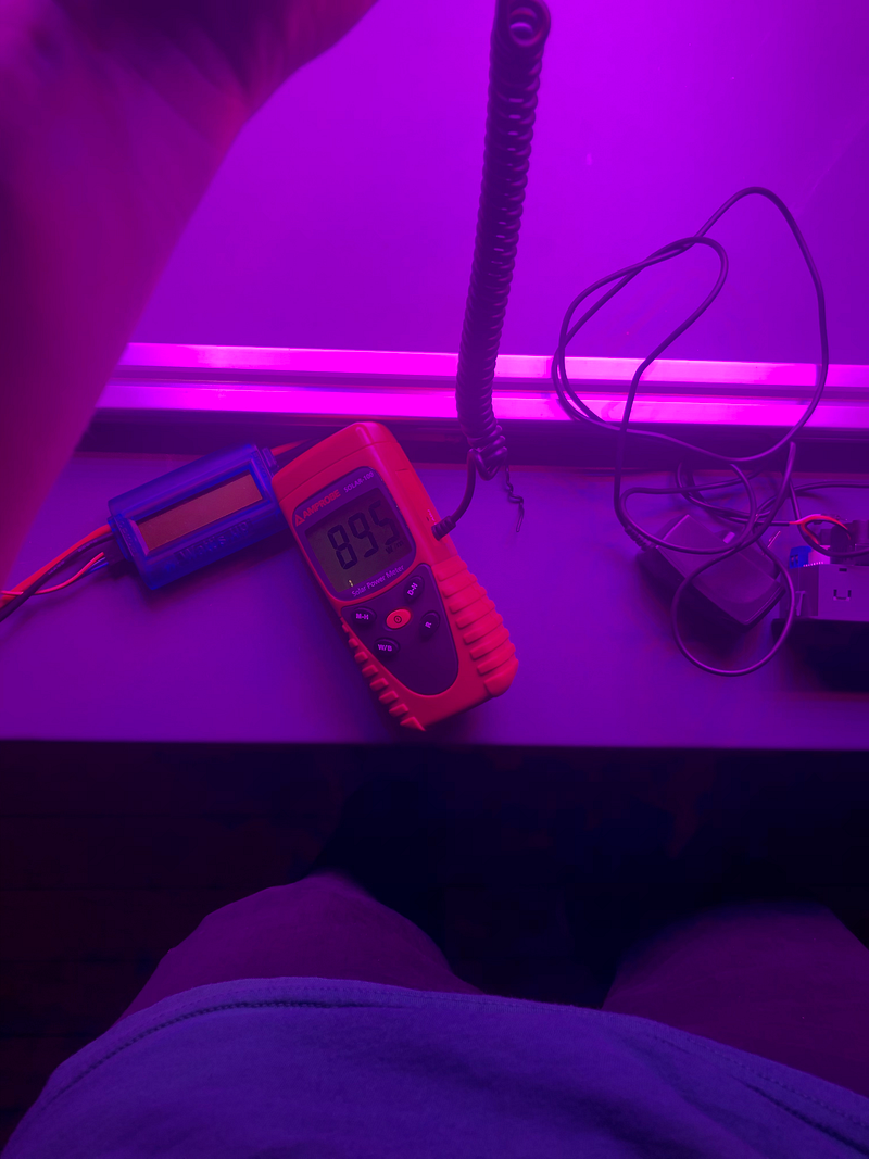
The standard measurement for direct sunlight is 1000 watts per meter squared. Often, people will try to test their solar projects next to a window. Let’s see how that measures out.
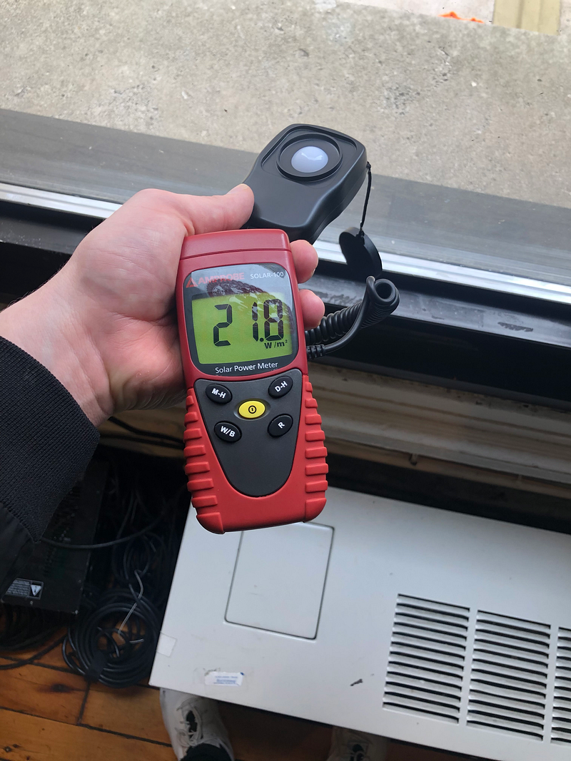
Now let’s try right outside the window.
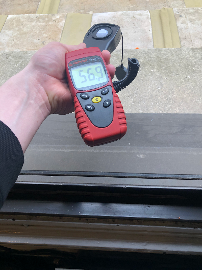
Still not great. If you’re not in direct sunlight, your watts per meter squared will decrease veeeeeery rapidly.
Growth Setting
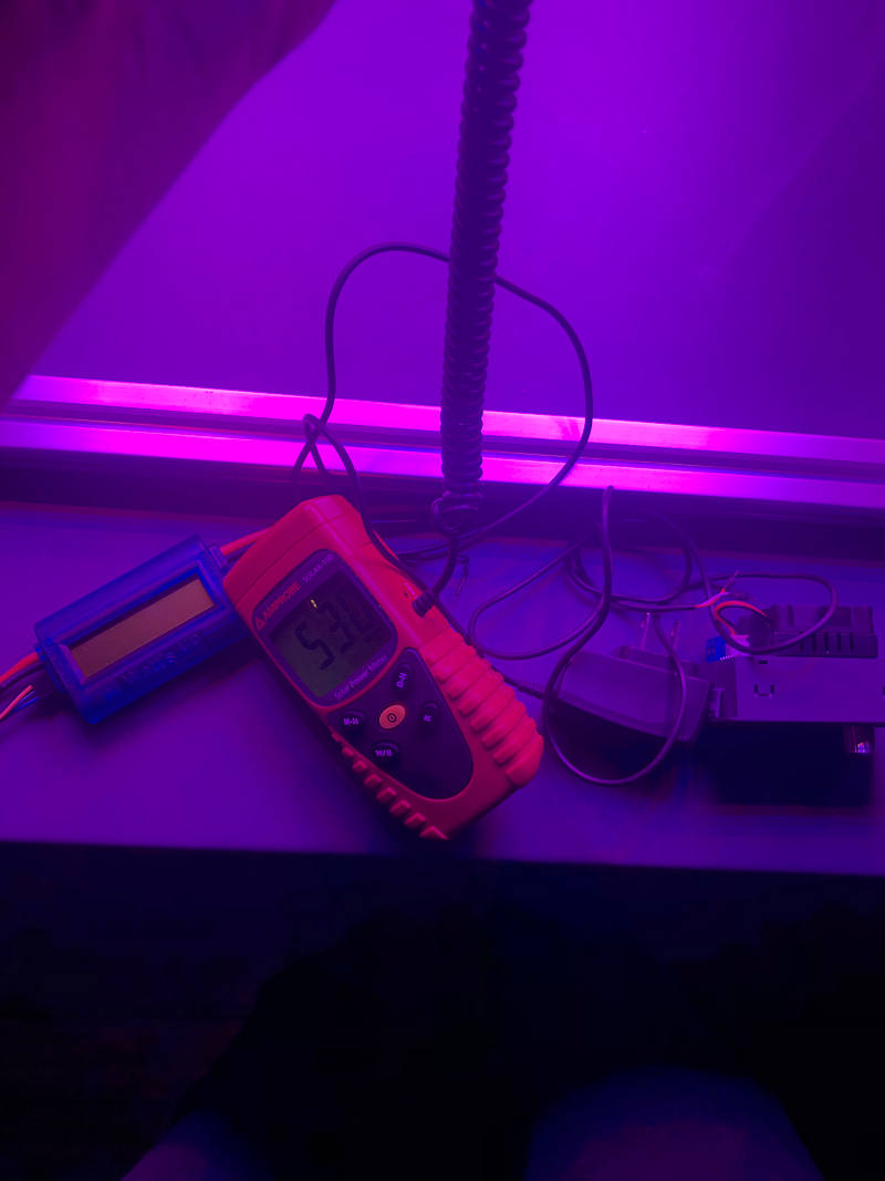
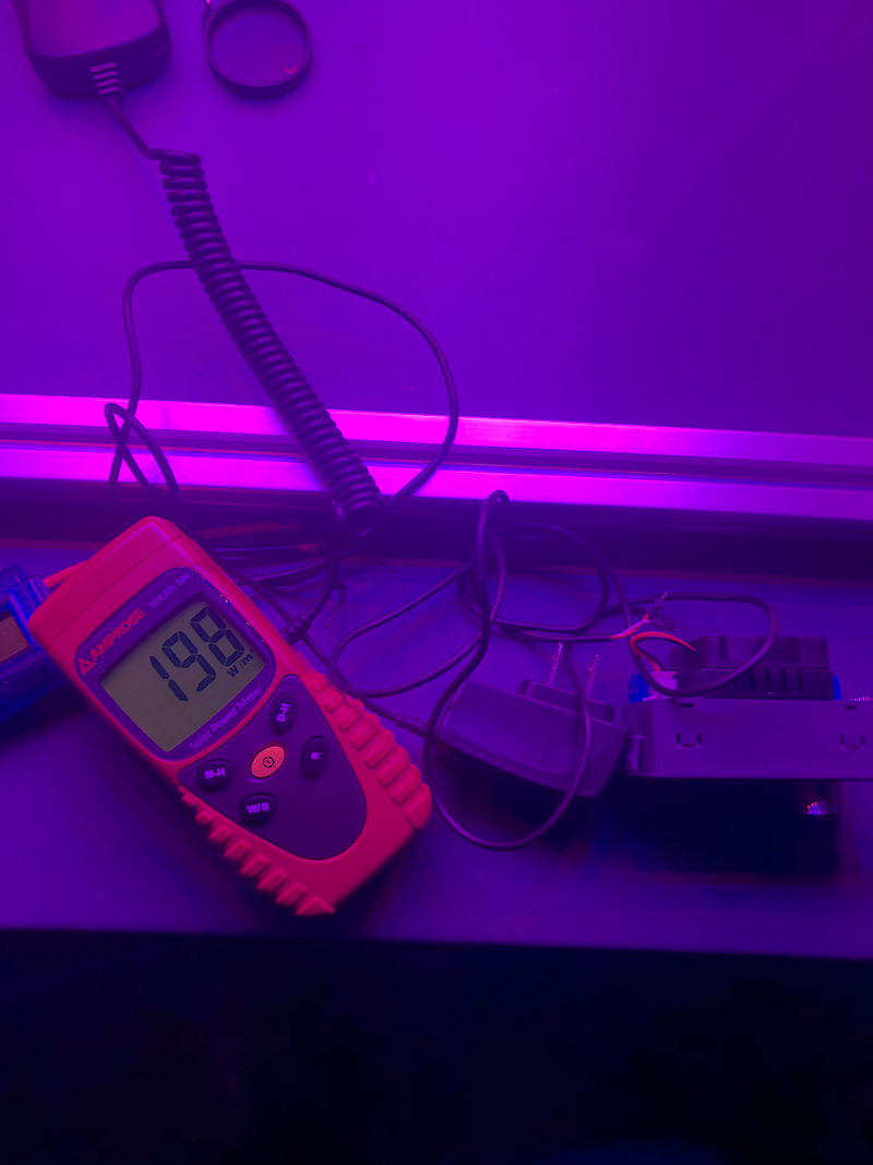
At this setting, if we place our meter right up to the LED panel, we get about 530 W/m2 — around half the wattage of direct sunlight. However, if we move our meter even a foot away, that measurement drops to about 198.
Bloom setting
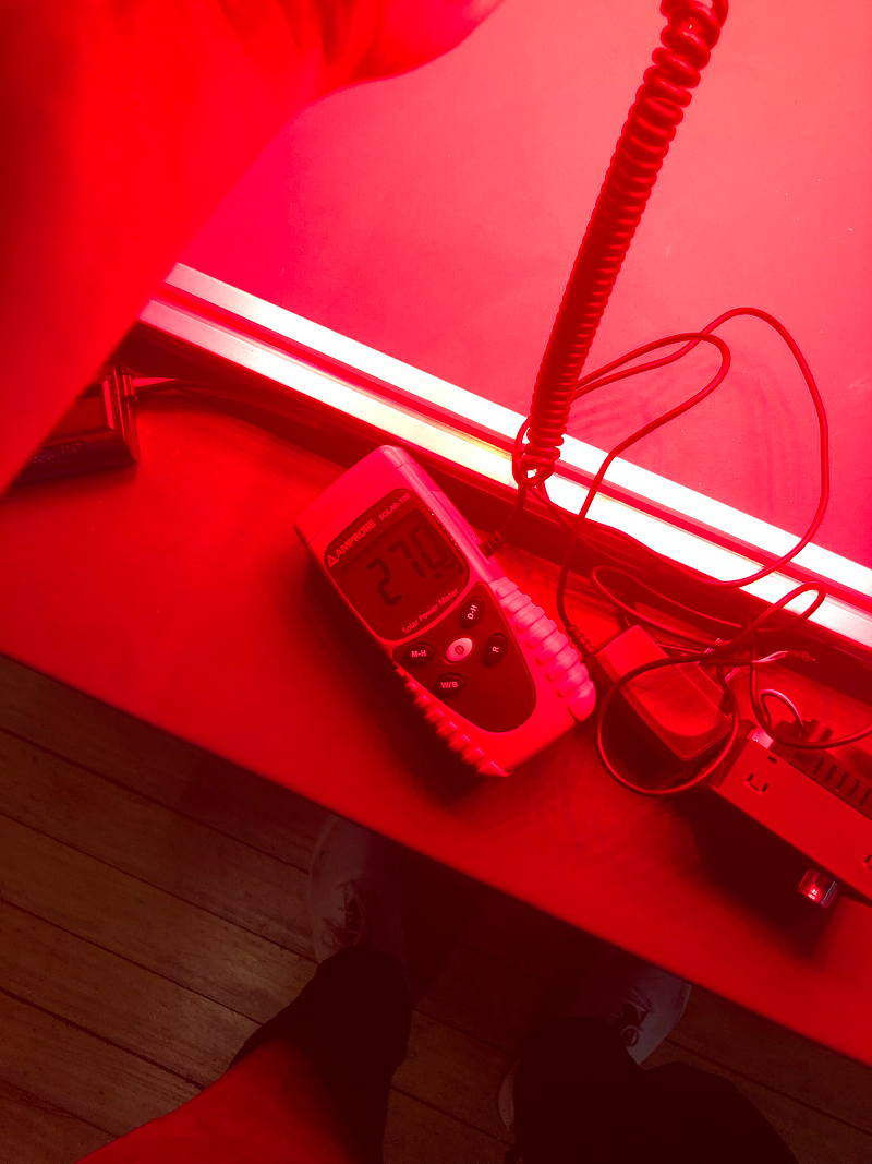
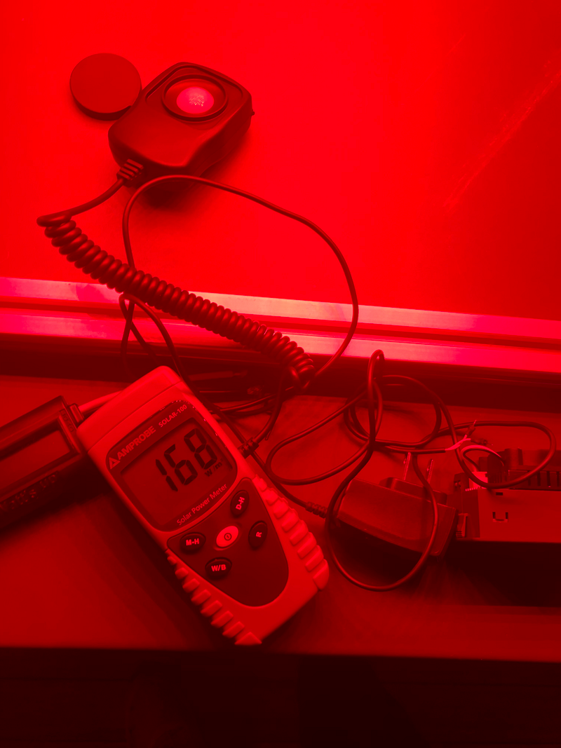
The bloom setting gives us waaaay lower light. So what do we do to get close to the sun?
Both switches on
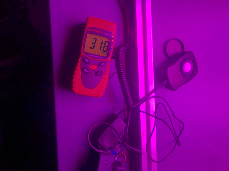
Now we’re getting somewhere useful. Still, if we move our meter even a foot away from the panel, we lose well over half of that wattage. This could be useful for testing low-light scenarios, but if we want to test for direct sunlight, we’re going to need to be as close to the light as possible. Luckily, it’s adjustable for just that reason.
Setting Up Your Project
Step 1: ADJUST THE LIGHT
First, measure the height of your project to determine how close the light needs to be to it.
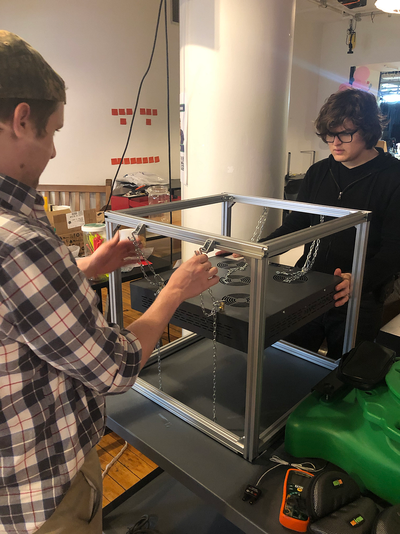
Then, very carefully, with ONE OTHER PERSON HOLDING THE LIGHT, take turns adjusting the chains on each side to lower the light. Just unhook the chains from the S-hook attachment and rehook them at a lower or higher height.
You can now put your project under the light. But DO NOT TURN IT ON YET.
STEP 2: TURN ON THE FAN
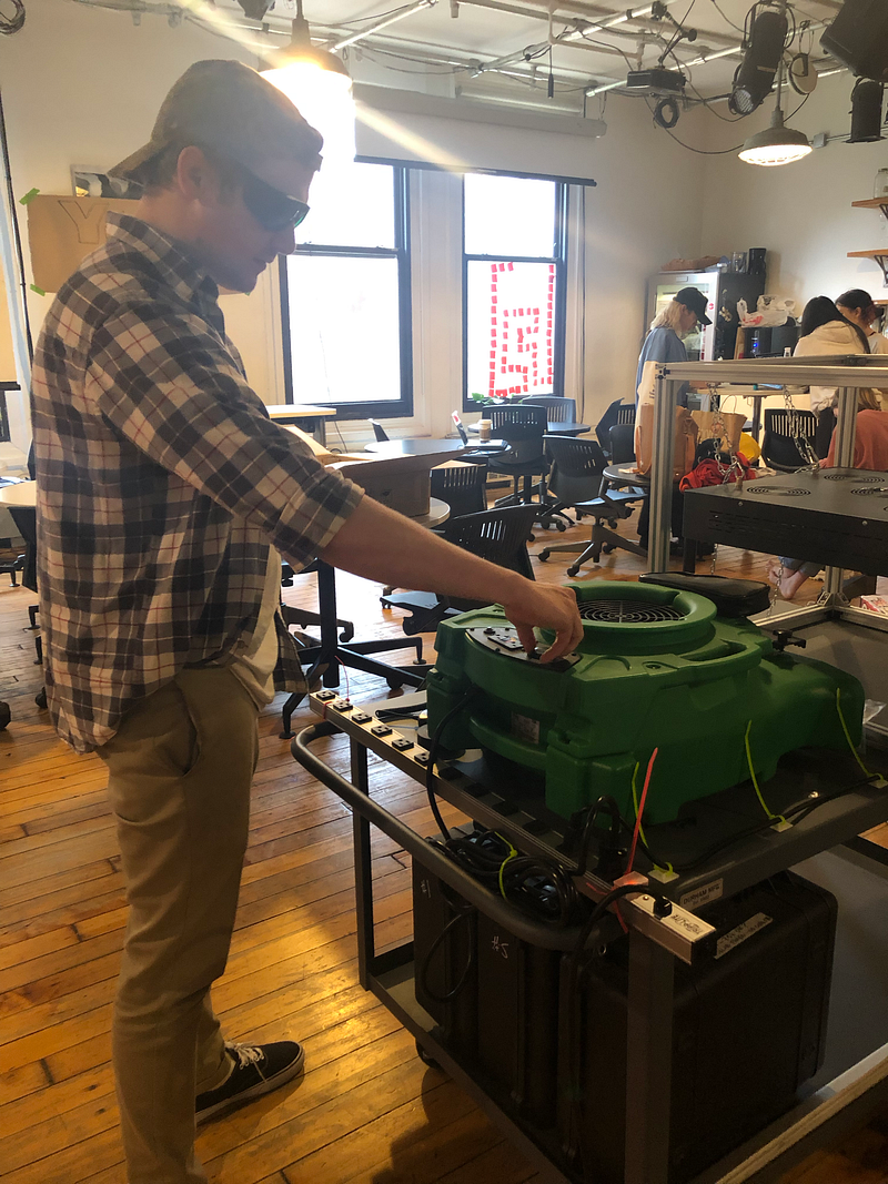
Next to the light, there’s a big green fan. Make sure this is on and blowing air before you turn on the light.
STEP 3: TURN ON THE LIGHT
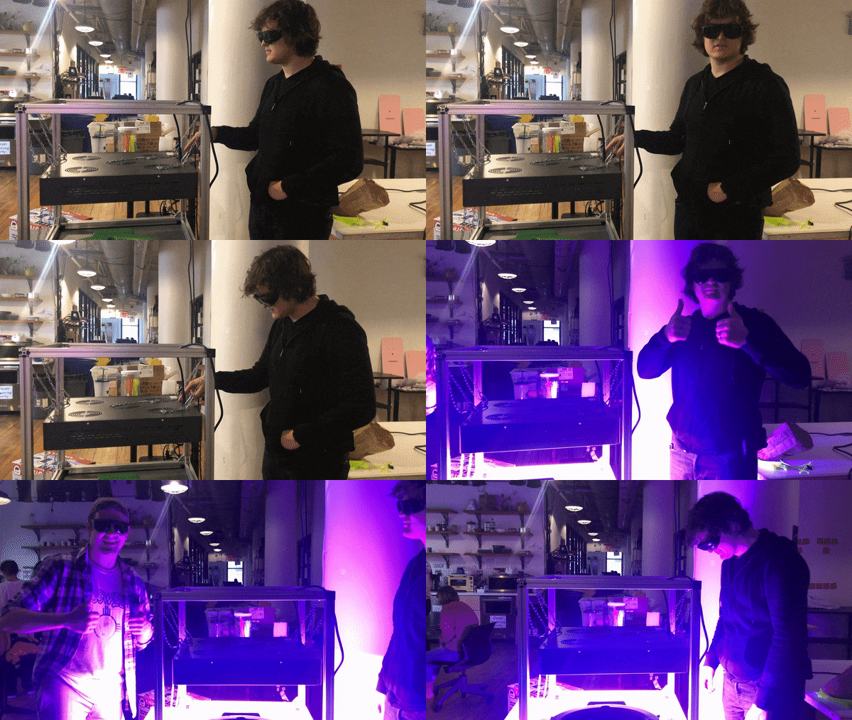
Congrats! Your project is ready to go.
Equipment (in the bin underneath)
Drok USB intelligent electronic load — great for testing projects with a variable load, or checking if a power source can power something before you buy it.
SunTransfer Solar Lamp/Mobile Phone Charger x5 (at least 2 broken) — I don’t know how old these are, but their website doesn’t work anymore, so it’s anyone’s guess how well they work. Could be fun to take apart!
Adafruit 6V/6W solar kit x4 (kit 1 currently missing DC/DC converter) - These are probably going to meet most of your solar project needs in an ITP context.
SunTransfer 9V/2W panel
Watts Up watt meter — This is an incredible device that you should use in any project where you’re measuring energy consumption. Some basic instructions for setup are below.
Tempest Security Battery — this is a big-ass battery, if you need one of those.
350 farad capacitors & individual solar cells in cardboard box
KillAWatt PSx — electricity usage monitor, good for monitoring project consumption over a longer period of time or just solving your curiosity about how much power your macbook consumes.
Open Circuit Voltage With A Solar Panel
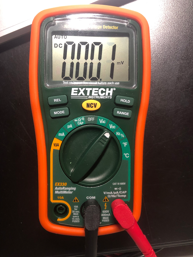
On a multimeter, connect the black wire to the COM socket and Red to the standard voltage socket, usually found on the right side. Set the multimeter to measure DC voltage.
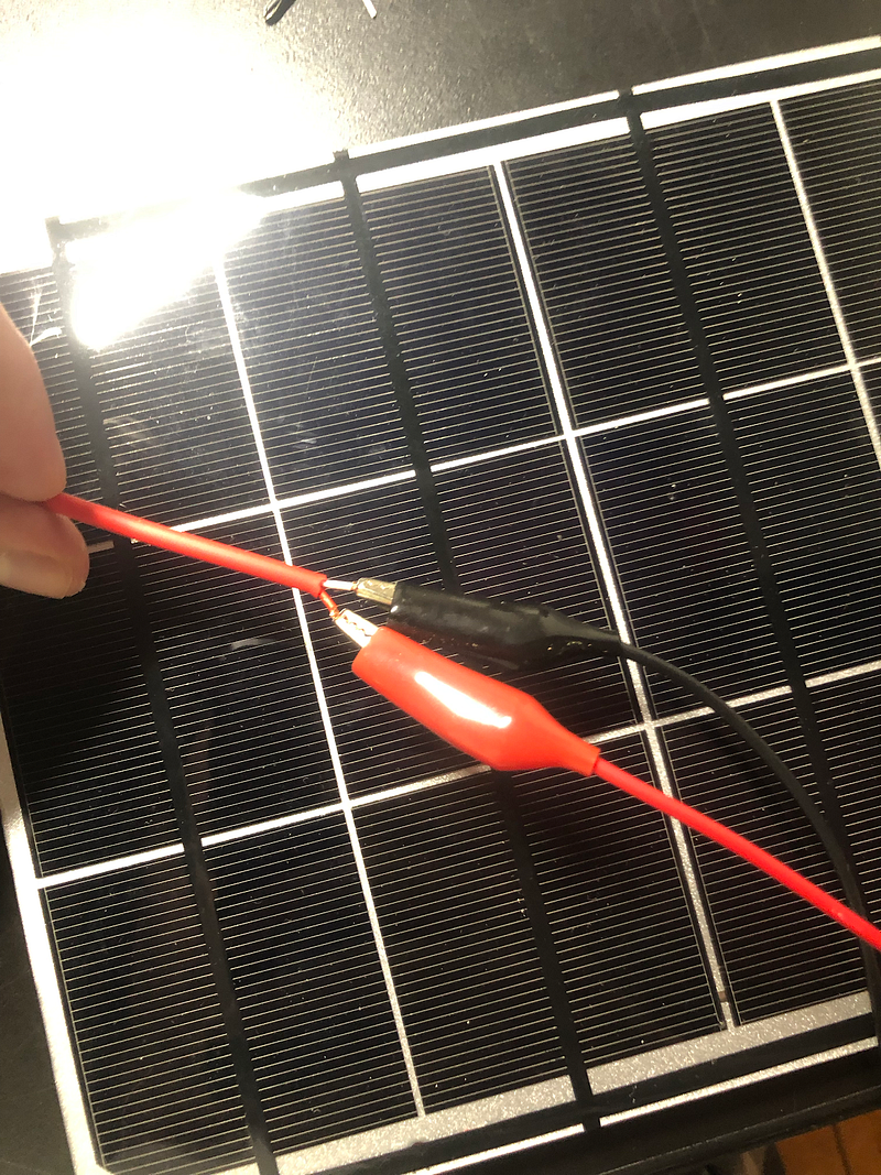
Using your handy alligator clips, which you definitely remembered to buy, connect your voltage to the red wire on solar panel and ground to the white wire.
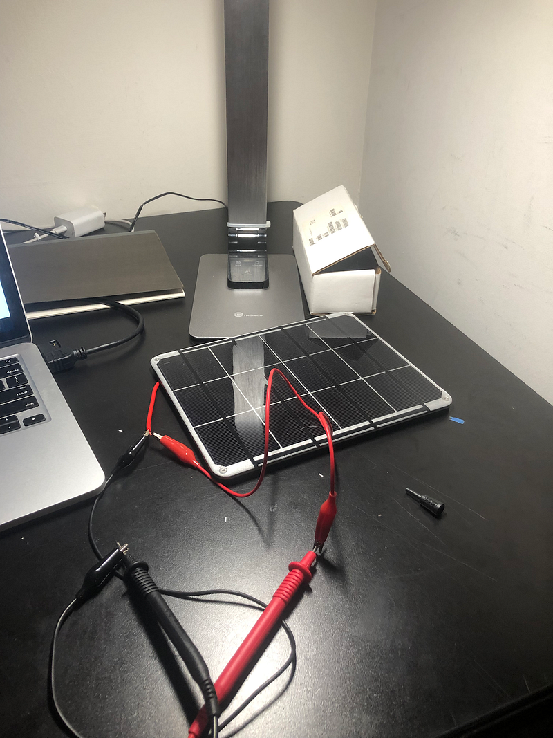
Congrats! You can now measure your solar panel’s output. If it’s working correctly, it should give you a decent output. Using one of the 6V Adafruit solar panels, you’ll get about ~5V if it’s close to an indoor lamp.
Short Circuit Current With A Solar Panel
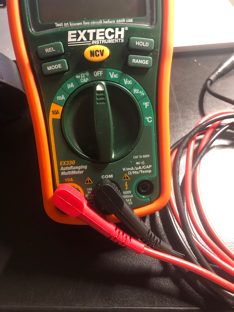
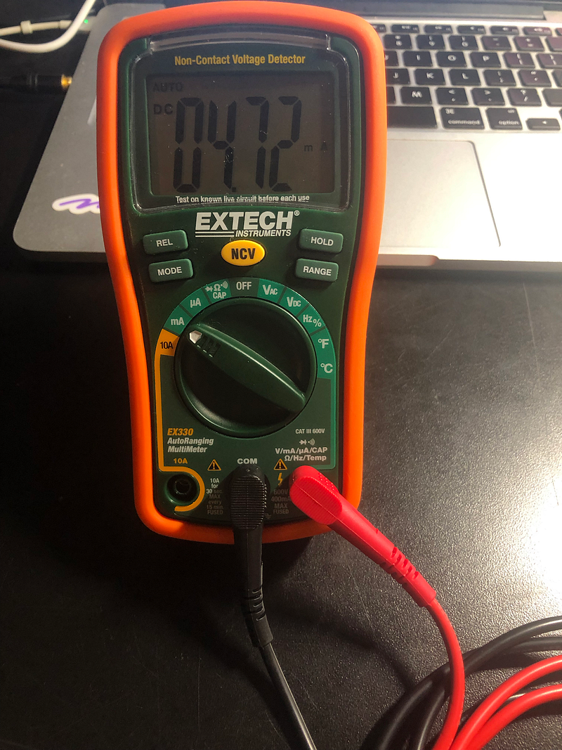
Keeping your multimeter attached to the solar panel, switch the red cable to the 10A socket, usually found on the left. Set it to the 10A measure setting.
This may not work out well, depending on the current your power source is putting out. However, there’s an easy fix for that!
For low-power current sources, simply switch the red cable back to the standard output, and try measuring microAmps and milliAmps. If you’re getting any current at all, it should show up. For example, on one of the AdaFruit 6V solar panels, I get about 5 mA under a standard LED lamp.
Still confused? Check out this helpful video: Solar panel: how to measure open circuit voltage & short-circuit current.
Measuring A Battery While It’s Being Charged/Measuring Energy Consumption Over Time/Measuring Pretty Much Anything With The Watt’s Up
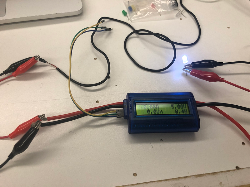
Meet the Watt’s Up watt meter. If you’re doing an energy project, you’ll want to be best friends with this guy.
This meter measures current, voltage, and time, and calculates peak current, peak power, minimum voltage, power (W), energy (Wh)and charge (Ah) values on any circuit you attach to it.
Setup
Simply attach your power source to the “source” wires on the left of the screen and your load to the “load” wires on the right.
Testing low-power batteries (anything below 4V)
If you’re measuring a power source below 4V (which is going to be a lot of the LiPo batteries used in ITP projects and any smaller batteries like a coin cell), you’ll need to connect the auxiliary power on the Watt’s Up to get accurate measurements — the three wires on the left side by the “source” wires. These should be marked, but since things at ITP are rarely the way they should be:
The blue wire furthest from the source input is ground.
The green wire in the middle is the voltage input.
The yellow wire closest to the source input resets the Watt’s Up.
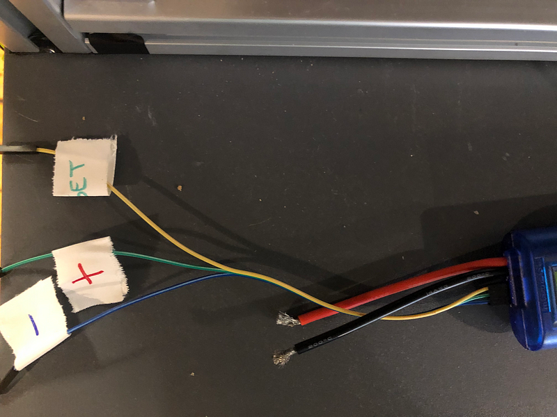
These can easily be connected to a wall power source or a 9V battery — anything above 4 volts should do.
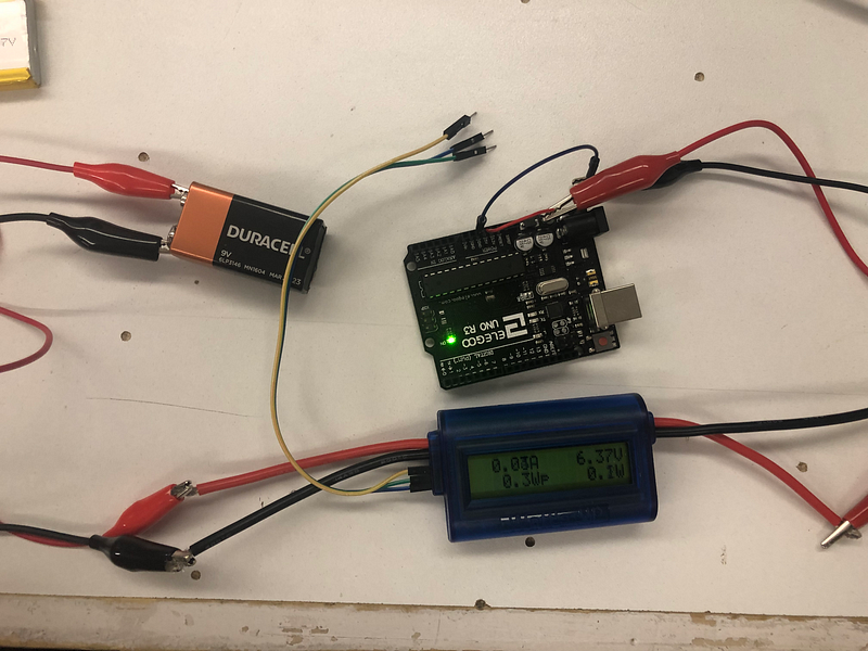
In the extremely confusing picture below, I’ve:
- attached a 3.7V LiPo battery to the “SOURCE” input.
- attached an Elegoo to the the “LOAD”.
- attached the wires from a wall charger to the Watt’s Up auxiliary power source.
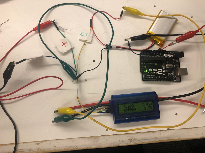
This way I can get accurate measurements from my low-power battery.
Still confused? The Watt’s Up manual (TODO: find permanet file storage for PDF) is extremely detailed and helpful if you run into any issues.
Measuring Variable DC Load With The Drok Intelligent Electronic Load
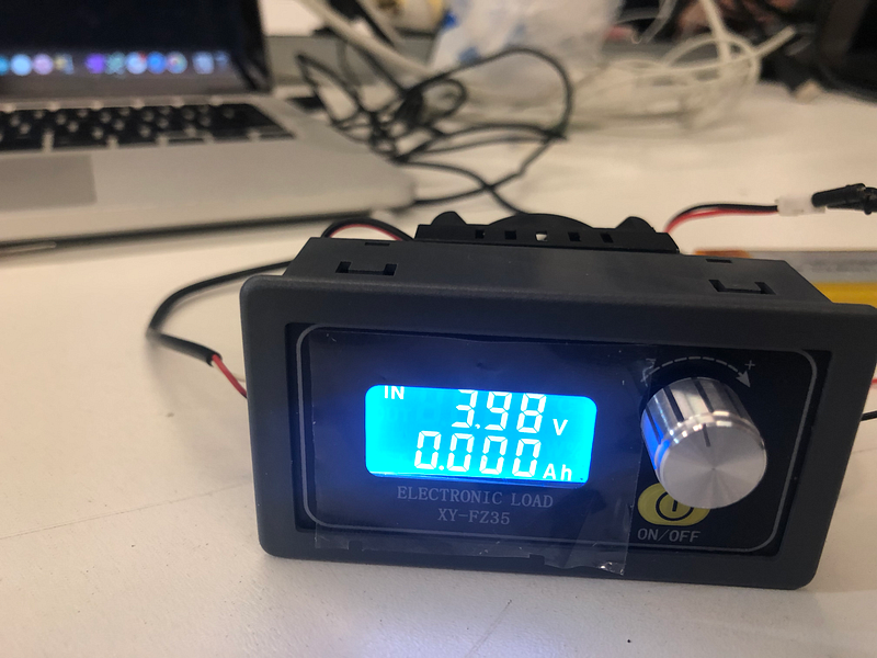
This is a crazy little machine! It mimics an electronic load on a power source so you can check how it will perform in different power consumption scenarios. To set it up, connect the VOLT connectors to a reliable power source (a wall charger should work fine) to power the electronic load itself, then attach your battery or other power source to test its performance.

As you can see here, I’ve attached it to a 3.7V LiPo battery, which should offer 2 amp hours when fully charged (so it should last two hours with an output current of 1 amp).
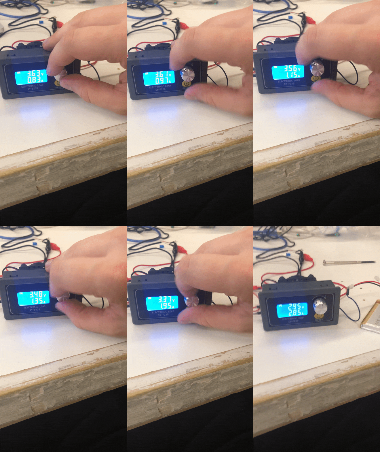
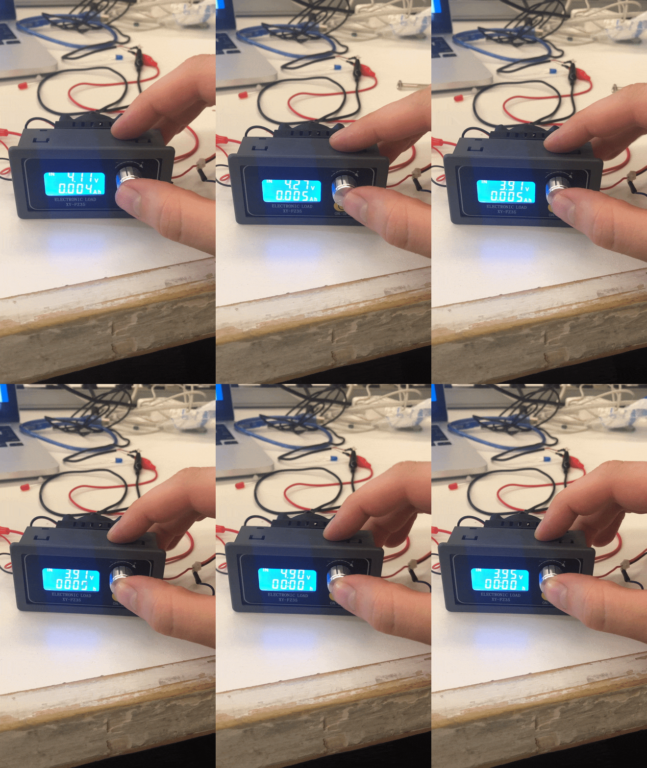
By rotating the dial on the front, I can increase the current draw of the electronic load, and by pressing down on it, I can check the wattage, amp hours, and hours left of charge at the current draw on my power source. In this example, it’s only measuring 00.05Ah on my battery — chances are the battery either needs charging or isn’t very good.
Helpful resources: https://www.dummies.com/programming/electronics/how-to-measure-voltage-on-an-electronic-circuit/
https://www.dummies.com/programming/electronics/how-to-measure-current-on-an-electronic-circuit/
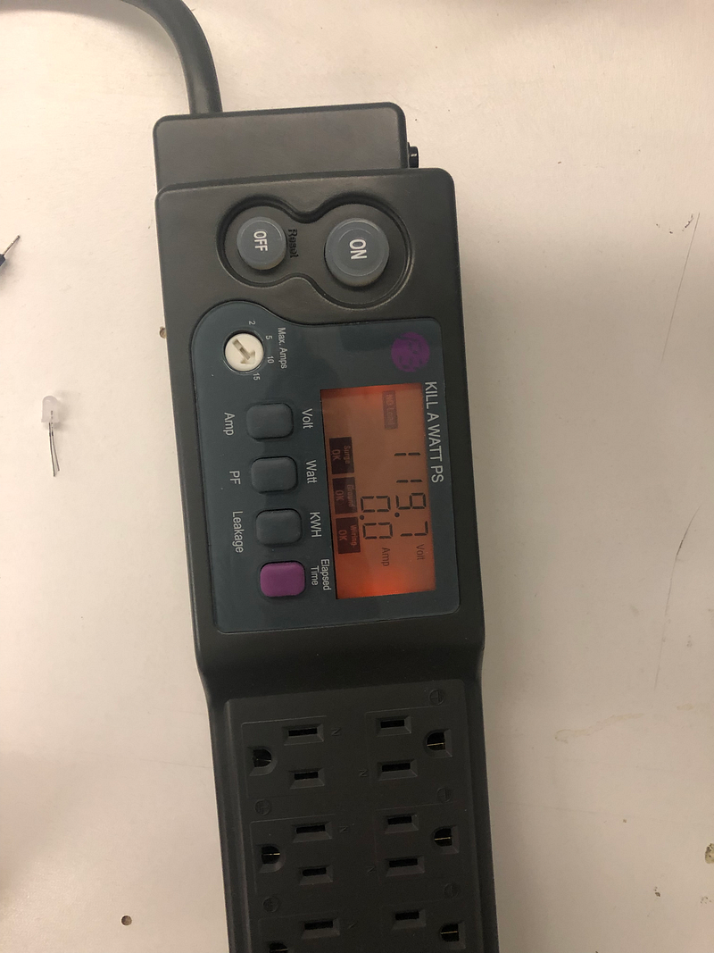
This thing is a lot of fun and a great way to measure long-term power consumption on larger projects. Simply plug it into a wall socket and plug your project in, and it’ll give you tons of information about its energy consumption and efficiency: voltage, amperage, power factor (the percentage of available energy being consumed), kilowatt hours of power consumed since it’s been reset, and leakage (amount of power in the circuit returned to ground).
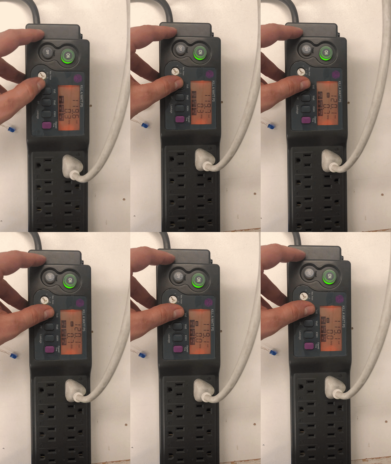
If you cycle the button for each, it’ll also give you the minimum and maximum values recorded. If you have a project you want to leave plugged in for an extended period of time, this is a great way to track its energy consumption.
You can check out the manual here.