The Solar Plant(er)
by Rashida Kamal, James Hosken, and Brent Bailey
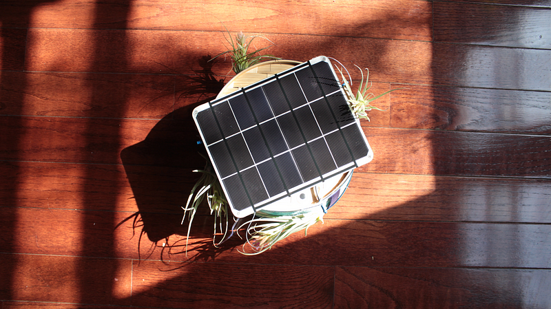
For the solar challenge, we decided to make a planter that seeks the sun. In retrospect, combining solar power and robotics is more difficult than we may have anticipated, but why not shoot for the stars when working with solar power?
Ideation
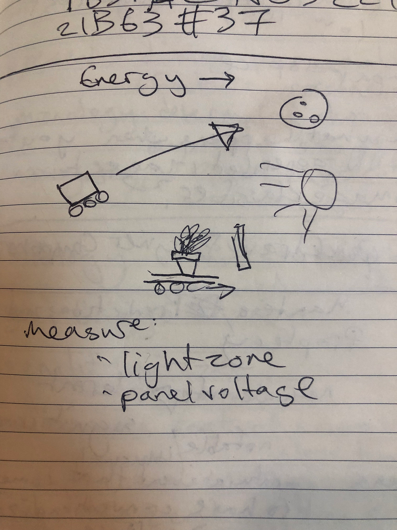

We decided to accomplish this we’d need something that performed the following functions:
- Charged a battery using a solar panel.
- Drew no or extremely low power for a significant enough period of time to charge the battery.
- Was able to intermittently power DC motors to move wheels.
- Was able to detect sunlight and move towards in during the intermittent “on” phases.
How — Basics
Fabrication
For our basic materials, we used an Arduino Uno with a motor shield and Adafruit’s DC Gearbox motors with two hobby all-terrain wheels, plus one of Jeff’s solar panels with a solar lithium charger.
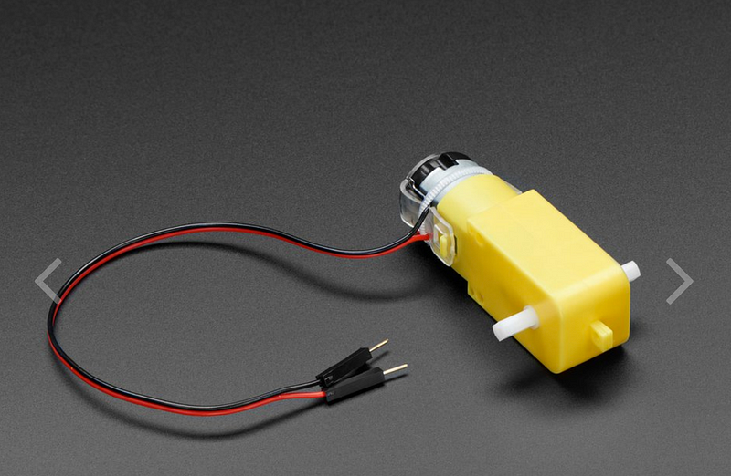
For initial prototyping, we attached all this to the top of a laptop case, drawing power from James’s battery, which gives 2000 mAh and 3.7V. We used simple breadboards to get the initial circuitry figured out. Since we didn’t have LDR’s attached to the initial circuit, we added an ultrasonic sensor to prevent it from running into walls. This kind of worked.
This version met our basic needs: it was mobile and battery-powered.
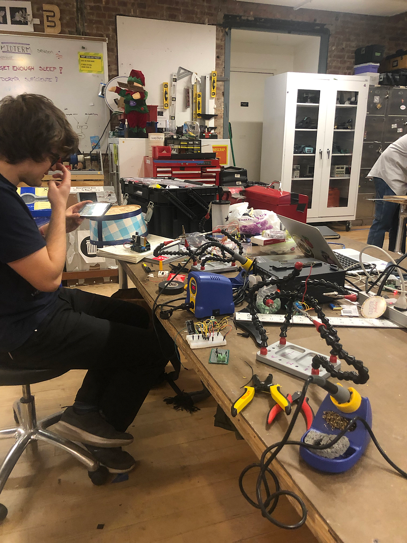
For our final version, James and Rashida (with a small amount of help from Brent) spent a truly excessive amount of time soldering the circuits onto custom PCB and attaching everything.
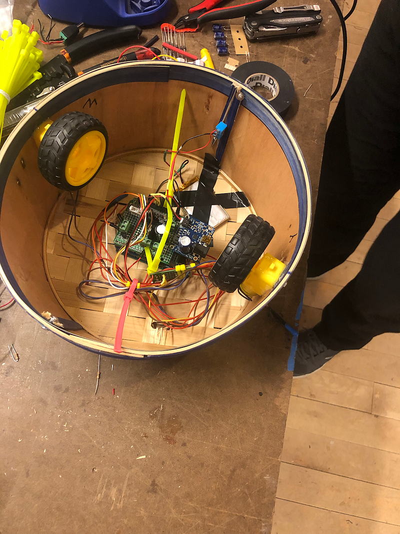
This we put inside a basket from K-mart, hot-glued on the wheels, tied the solar panel to the top, and for #aesthetics and also so that it technically did what we set out for it to do, we sewed on four air plants at its corners.
Behavior
You can check out the final code here. Basically, the arduino takes input from 3 light-dependent resistors and chooses to move forward, left, right, or remain where it is based on which LDR is receiving the most light — we used a simpleKalmanFilter to normalize these values since the LDRs are prone to fluctuation. While we’d initially hoped to run the timing circuit based on a 5–5–5 timer, we ended up having to use AdaFruit’s SleepyDog library to initiate a sleep mode while the battery charges — this has a power draw of about 4 microamps on a 3.3V power source, which is pretty negligible. As it stands, at an interval of N (for testing we’re using 10 seconds, but in ideal conditions it would happen every few seconds), the arduino powers on, activates the motor, and chases the light for 10 seconds, then goes back into sleep mode. This process involved a lot of tweaking for speed and light input — as you can see from some of the videos, it would initially move more than it needed to or over-turn, and the LDRs gave out inconsistent values even with the SimpleKalmanFilter.
(CRAZY TURNING VID, DRIVING INTO TRASHCAN VID, VID_4594 HERE)
We added comparison code and a broader range of input values for the default condition (remaining static) to resolve these issues. We also found that covering them with heat shrink to reduce the amount of light entering them helped us get more consistent values. This resulted in a much more responsive (but less over-reactive) movement loop.
(FINAL VID HERE)
How — Circuitry and Optimizations
Hardware
Modules:
(See diagram)
LiPo (2Ah)
PV Panel
Solar Charger
555 circuit
TIP120 (*)
Large Capacitor
Motor Shield
Powerboost
Arduino
Main System Problem Encountered:
- Once soldered, the Powerboost did not turn on reliably.
Assumptions About Problem:
- Not enough Voltage (or Current?) to Powerboost after soldering all components.
Solutions Tried:
- Replace TIP120 with N3904.
- Worked slightly better, still not enough to power motors
- Replaced TIP120 with MOSFET (IRF740)
- Did not work at all (**)
- Boost output of 555 with N3904
- Sleepydog with workaround for Motorshield (Implemented solution)
- N2222 (600ma continuous max) Base to pin 4
- Collector to Vcc (Load pin on Solar Charching Circuit)
- Emitter to Vin on MotorShield
- Motor shield now only turns on when arduino is on (slight code modifications)
Steps for the Future:
- A MOSFET would likely work with a different circuit order. If the Source of the MOSFET connects directly to ground, with the Drain connected to the GND of our ‘Load’ (i.e. the whole circuit), we may have more success.
* TIP120 = darlington.
** MOSFET works on difference between gate and source. In our layout the circuit would not work as there is no discernable voltage difference in the circuit.
// Code //
James code modifications:
- interval timer for sleepydog (on 10 sec off 10 sec)
- motor ease in
555
One of the ways we tried to conserve power in our Power Plant setup was to use a 555 timing circuit to manage the power to everything else. Before diving into the myriad problems this led to in later stages of our project, I’ll briefly shared by we choose the circuit configuration we did and what we hoped to accomplish.
We relied heavily on the follow tutorial: Electronics Tutorial: 555 Oscillator. A few experiments with alternative configurations revealed that we would need to use an astable configuration with a few modifications. The 555 oscillator uses a an RC circuit to create a square wave output on pin 3 of the 555 chip. Adjusting the values of the resistors allows you to change the duty cycle of the square wave, and in our case, we wanted to ensure that the duration of our output was low much longer than it was high. In order to accomplish this, we “isolated” the discharge resistor (R2) from the rest of the RC circuit, so that the capacitor charged through R1, but only discharged through R2. In this configuration, we were able to see a 3-minute on, 1.5 hour off cycle by using 20k ohm resistor on R1 and a 500k ohm resistor on R2.
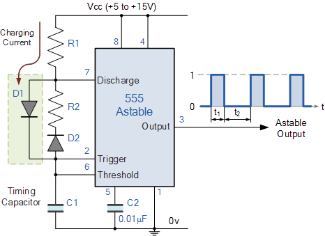
(Source: Electronics Tutorial)
Theoretically, this meant that we could power the rest of our electronics for only 3 minutes, and then, sit idle for about 90 minutes. In our initial tests, this saw an amperage draw of 2 mA in the off state and 300–350 mA when the motors were at work, loaded. Because our solar rover would only need to adjust its position relative to the sun from time to time, this seemed to be an ideal solution.
However, we ran into a great deal of problems once we moved off the breadboard to our soldered and fabricated model.
We had been sending the output of the timing circuit to trigger a TIP120 (Darlington) transistor, and though this seemed to work with initial setup, in the latest iteration of the rover, the timing circuit does not seem to provide enough amperage to power the motors. We suspect our own soldering and added additional load of the final construction may have been factors at play.
We also tried to use voltage controlled MOSFET transistors in place of the Darlington, but quickly ran into the limitations of our own understanding.
Minimal version that worked: https://youtu.be/sqxfThuVjVo
Voltage Reading from 555 Timing Circuit: https://youtu.be/xGN61LF24iY